
FIRST, IF YOU WANT, YOU CAN DOWNLOAD THE NAVAL DRAWING TECHNICAL PDF CATALOG:
Those of us who have a condition of maritime modelling many times, as we walk along some of our beaches, see some boat that we would like to build.
We look at it and yet we don’t know how to do it to get an acceptable shot out of it.
This modest treaty, by way of summary, will try to solve this gap and make you (hard reader) a good naval technician.
The first thing you have to do is go to the boat in question, take measurements of the total sleeve, the maximum height from bow to stern and the central one, which will be the minimum.
Once at home, you will make the useful custom of the boat under study. (Fig. A and B).
In cases of large strut and deck boats you can take measurements on the outside as you see in the (Fig.C).
The utensil, according to the attached drawing, will be of a ruler a little longer than the boat hose, and another slightly longer than the height of the bow, which will be joined at an angle of 90o. (See Fig. 1, No. 10).
The vertical ruler will carry guides every 10 cm or 20 cm to support a solid wood (metric tape shape), to take measurements.
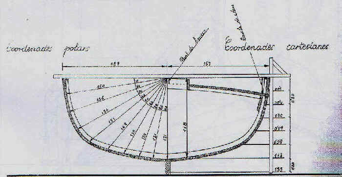
Figure A

Figure B
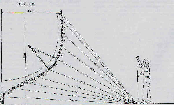
Figure C
To make the description serves as a model a “gussi” of a 4.18 m long.
In the field drawing (No. 1), you can see that we take measurements on the outside or by Cartesian coordinates.
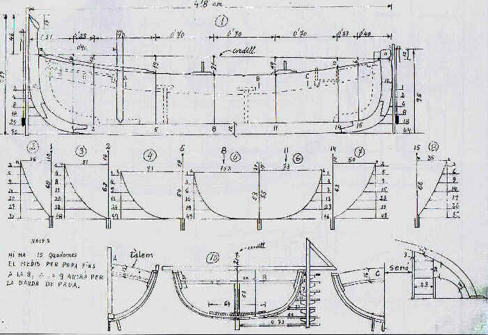
Figure 1
Materials we’ll need: a tool like the one described, string, 1 cm wide roll of adhesive paper, one meter, a tape measure, a plumb, square, notebook and pencil.
If it is windy it is good to wear white cartons of a folio format, which do not fly so much.
Fieldwork. We’ve reached the beach and we’re in front of the boat.
First we will put the string tied from bow to stern in the manner indicated in the drawing (No. 1).
Next we will draw the profile of the boat in an approximate way.
We will divide the length of the boat over the already placed and properly stretched string so that the divisions fall on the center of the 1,2,5,8,11,14 and 15 headbands.
If you take attention you will see that both bow and stern, measurements are taken more together by the great afuamenta that has the boat in both limbs.
The centers on the string will be marked by anganxing there a few small cuts of fat paper.
We will stick strips of the same paper in the center of these quadernal is, (see drawing), from the keel to the boat’s embroidery, duly stoned to follow the center of the quaderal.
With these instructions we will have the boat ready to take the corresponding measures.
What is a line plane? :
The ship’s line plane is the described element, which graphically demonstrates the characteristics of its shapes.
It is composed of three projections: longitudinal, transverse and horizontal, which must be made at scale to allow to obtain, easily and without room for confusion, the lines.
The lines will be rectified to each other and we will transfer them to other papers or directly on the wood to build the ship.
First, we’ll explain the three projections, which shape the ship.
Longitudinal or profile projection:
The line plane represents, in longitudinal projection, the profile of the ship’s hull.
In addition to its contour, it is determined on it, the waterline and a series of parallel lines called water lines, spaced evenly, which are marked from bottom to top with numbers from 1 onwards.
The waterline and the water lines below it are drawn with continuous traces.
Those above the waterline are false and are represented by interrupted or discontinuous traces. (See field drawings No. 2 and 3).
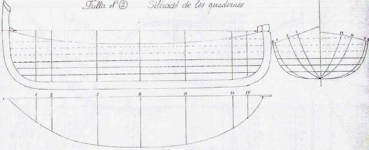
Figure 2
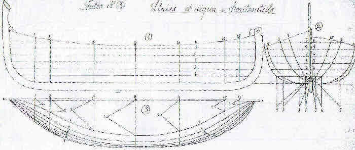
Figure 3
The longitudinal profile also shows the cross sections, which correspond to the plot bearings, represented by lines perpendicular to the water lines.
They are usually separated by equal distances and are numbered starting from the left.
Also in this projection are curved lines that correspond to the profiles of the vertical or longitudinal sections, which we will see now represented in the horizontal projection and that are marked with Roman characters. (See field drawing No. 4, the plane of longitudinal shapes.)
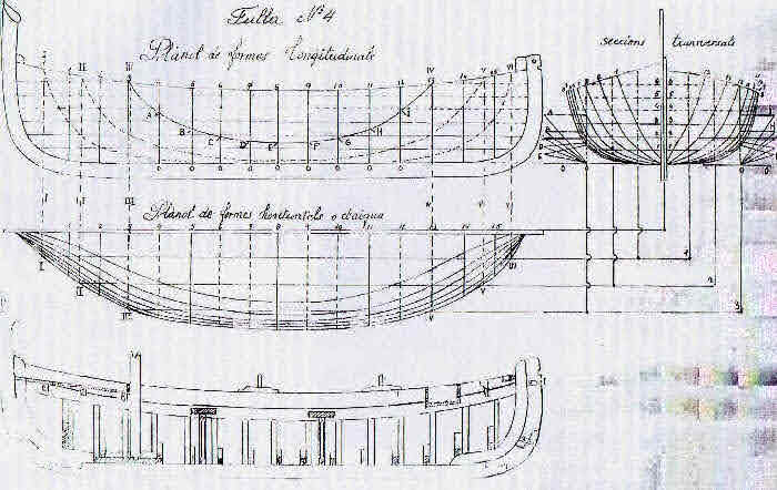
Figure 4
Horizontal or plant projection:
It is usually drawn below the longitudinal to horizontal projection, which corresponds to the representation of the vessel seen from above.
Figure in this projection the cross sections, as an extension of those indicated in the longitudinal projection.
From a crunch line or axis of symmetry, directed from the middle part of the stern, to the point of convergence of the bow and parallel to it are appreciated the vertical sections, which correspond to cuts perpendicular to the water lines.
The limits of these, when cutting the ship produce the curved lines, marked with Roman numerals already mentioned in the vertical projection. (See field drawing No. 4, horizontal shape plane.).
Also in the horizontal projection are shown curved lines that correspond to the water lines and represent the different parallel planes, which cut the vessel horizontally, and provide different contours, according to the theoretical levels that it would catch, the water on its sides in different immersion situations, always considering it in identical directing situations.
Both vertical section lines and water lines are drawn only in the middle of the horizontal plane, as they are symmetrical paths.
Cross-sectional projection:
Although each projection has individual characteristics, it can be said that with the graphic data contained in this plan and in those represented in the longitudinal profile, which indicates the separation of the headbands of the path, the water lines and the wheel shapes and fastened, we could obtain the necessary templates to build and verify our helmet.
This cross-sectional plane is usually placed on the right side of the drawing and comprises the cross sections or plot paths, which are the surfaces that we would obtain if it proceeded to saw the vessel perpendicular to its horizontal plane following the line of each of the sections numbered from the 1st onwards.
There are more lines to describe, however, I don’t want to overwhelm you anymore.
Explained the theory, we can put ourselves back in front of the boat and start taking the measurements.
Well, let’s go there.:
Ready the string (see field drawing No. 1, drawing 1) with the chosen gaps, we will place the tool that we have prepared on the center of the headboards, (starting with the first one) and fastened to the embroidery and the horizontal ruler resting on the embroideries of the boat. (See field drawing No. 1, drawing 10).
Let’s start taking the measurements::
According to field sheet No. 1., in drawing 2o, the taking of the measurements of the 1st head is described as follows: under the horizontal ruler up to the string you will see that it marks us 10 cm; this measure of the wrinkle; under the ruler up to the keel mark 68 cm. strut; from the center of the string up to the overboard 36 cm.; and from the embroidery to the keel (to know the curved shape of the headband) the 1st size mark 2 cm.; and successively 5 cm., 9 cm., 14 cm., 20 cm., 27 cm., and up to keel 35 cm.
The measures we have taken in the 1st city will be taken at the 2nd, 5th, 8th, 11th, 14th and 15th.
We will also take with the ruler and plumb the shapes of the wheel and the elbow, and its heights, thicknesses and widths.
With the tape measure we will take the length of the boat, and the distances between the marks of the string (always pointing to the actual measurements, since later on the drawing table we will reduce, according to the chosen scale).
It is not necessary to repeat that all measurements of length, width and thicknesses of the benches, thalamus, drill, bow capping, etc. should be taken.
The thicknesses of the varengas and stemaners of the headbands.
The amount of cuadernas in the boat.
Until the middle is on one side and the other.
In short, everything it takes to make a plane more understandable.
Already on the drawing table with the field notebook, with the measurements limited to the boat and once you have chosen the scale to make the plan, we will start to draw the profile of the boat with the keel codaste and wheel.
We will mark the string and separate with the measurements that we have in the field notebook the headbands.
We will draw them with a vertical line, and to your right we will draw the headbands as you can see in drawing No. 2.
Keep marking a few lines that the more water lines you put on you will have more reference points to mark all the conditions.
Now, it becomes necessary to remove the water lines.
To do this we will go to drawing No. 3, drawing No. 2.
We’ll take the compass:
We will put a toe in the center of the keel, the 1st water line and the other end at the junction of the same line with that of the 1st head with the number 1.
Numbered triangular marks represent the bars.
Thus, we just need to do what the attached drawing indicates by making marks 1, 2, 3, 4, 5, 6 and 7.
Following the paintings, we will have the 1st line of water of the horizontal plane.
These operations will be repeated to the other lines marked in drawing 2o., (The one of the headbands), to finish the plane of water lines, and to be able to find the shapes of all the conditions that we need to mark, which we will find later.
After the water lines or horizontal, we will mark all the headbands, (the 15 cuadernas of the boat), both longitudinally and horizontally.
If this is done, we will use the compass guiding us with the drawings in drawing No. 4o.
We will start by placing a compass toe cap in the center of the horizontal plane keel , (that of the water lines), of the headband No. 3, and the other end to the crossroads of water line No. 1, (water lines are marked in the transverse plane).
We will pass the size to the headbands of the cross section, which will be marked with a point in water line No. 1, on the bow side and we will already have the first point of the head of No. 3.
Next we will return to the horizontal plane to take the reference in the 3rd street, the 2nd line of water.
We’ll move it to the 2nd line of the transverses.
This is repeated until the water line No. 6 is completed, which will give us the shape of the 3rd headband.
We will repeat the operation to 4, 6, 7, 9, 10, 12 and 13 and have finished all the cross sections as can be seen in the cross-sectional plane of drawing 4.
Longitudinal shapes::
They can also be removed with the compass (they could be taken out with the parallelx, but it is not so safe).
We’ll take the measurements on the cross-sectional plane.
We will take them from the bottom up following vertical line No. 3, and the junction with the headband No. 4, with the letter A.
We shall pass this measure longitudinally to the number 4.
We will continue to put the compass toe cap on line 0 with the B.
We will repeat the action with the C, etc., until we reach the Y to complete the longitudinal line.
The exit points the 1st line gives us the perpendicular of the water lines.
In short, in the drawings you’ll see ways to get the shapes out of a boat.
I hope that this explanation accompanied by the drawings will help you solve any situation raised to want to lift the plane of the boat from which you want to make your model.
If so, I’ll be satisfied.
Drawings and text by Xavi Carreras